
LM-79 Rörlig detektor Goniofotometer (spegel typ C)
LSG-6000

Högprecisionsrotationsarmatur Goniofotometer
LSG-1890B

Högprecisionsrotationsarmatur Goniospektroradiometer
LSG-1890BCCD

Goniofotometer för fordons- och signallampor
LSG-1950

Goniofotometer för trafiksignallampor
LSG-1950S

VAD Brandlarms visuella varningsanordning Goniofotometer
LSG-1930

Kompakt Goniofotometer
LSG-1200A

LED-Goniofotometer
LSG-1100
 Lysdioder och armaturtestlösningar
 LM-79 och LM-80 Testlösningar
 LED-drivrutintestlösningar
 Testlösningar för hushållsapparater
 Mobil- och nätverkstestlösningar
 Testlösningar för fordonselektronik
 Ljud- och bildlösningar och IT-testlösningar
 Kabel- och trådtestlösningar
 Testlösningar för stickproppar och uttag
 Lösningar för test av strömbrytare
 Lösningar för transformatortest
 Testlösningar för elektriska leksaker
 Energimätare testlösningar
 Testlösningar för motordrivna verktyg
Välj en organisation
att bläddra bland standarder
Abstrakt
Automotive electrical networks are subject to complex electrical disturbances including voltage drop, polarity reversal, high‑frequency ripple and transient pulses. Automotive electronic components such as ECUs and BMS must pass stringent power‑supply immunity verification before vehicle assembly. Conventional unipolar test power supplies cannot support bidirectional energy flow, and fail to fully replicate four‑quadrant electrical conditions in real vehicles, leading to obvious deviations between test results and actual on‑vehicle operating conditions. The Four‑quadrant bipolar voltage simulator is a high‑precision power supply simulation device supporting bidirectional energy flow. It enables seamless switching output of positive and negative voltage and current, accurately simulates dynamic voltage variation, transient pulses and polarity reversal conditions. It also features custom waveform editing, adjustable impedance and wide‑band ripple superposition. Adopting voltage‑current dual closed‑loop control and full‑controlled H‑bridge topology for four‑quadrant operation, it achieves bumpless transition between quadrants and precise voltage regulation to satisfy diverse complex power‑supply simulation test requirements. Taking LISUN LIS‑APS‑4010K300 Four‑quadrant bipolar voltage simulator as the research object, this paper illustrates its working principle and core features, analyzes its application value in automotive electronics immunity testing, and provides test references for electrical load tests of automotive electronic products.
Practical Challenges in Automotive Electronics Immunity Testing
During vehicle start‑stop, load dump, motor operation and harness impedance variation, the on‑board power supply system generates numerous transient electrical interferences. In 12‑V on‑board systems, not only positive voltage surges occur, but also reverse voltage pulses. Under certain conditions, equipment under test absorbs power and feeds energy back to the power supply side. According to standards including GB/T 28046.2‑2019, ISO 16750‑2:2023 and ISO 7637‑2:2021, automotive electronic components shall complete immunity tests against voltage fluctuation, polarity reversal, transient pulses and ripple superposition to verify functional stability under complex power‑supply conditions.
Ordinary programmable DC power supplies can only output power unidirectionally. They are incapable of absorbing feedback energy from DUTs, outputting negative voltage or completing polarity reversal tests. Their limited voltage slew rate makes it difficult to reproduce microsecond‑scale transient pulse edges. Some test solutions build test loops by combining storage batteries and signal generators. Such setups require complicated wiring, and battery internal resistance varies with charging‑discharging status, resulting in non‑adjustable output impedance and poor test repeatability. Test loops assembled by different operators introduce considerable measurement errors and fail to meet laboratory requirements for standardization and reproducibility. Therefore, the industry requires dedicated equipment with bidirectional energy flow, bipolar output, programmable waveform and continuously adjustable impedance. The Four‑quadrant bipolar voltage simulator is specially developed to address above‑mentioned industrial pain points.
Working Principle and Core Characteristics of Four‑quadrant Bipolar Voltage Simulator
Ocuco-landskapet Four‑quadrant bipolar voltage simulator adopts full‑controlled H‑bridge topology together with voltage‑current dual closed‑loop control algorithm to realize four‑quadrant operation. Seamless switching of positive and negative voltage and current is realized without disturbance or voltage spike during quadrant transition, so additional interference introduced by test equipment can be avoided to protect devices under test. Supporting bidirectional energy flow, the Four‑quadrant bipolar voltage simulator can output power to DUTs as well as absorb feedback energy from DUTs. It fully reproduces electrical behaviors of real‑world vehicle loads and overcomes the technical limitation of conventional power supplies incapable of handling regenerative energy.
The Four‑quadrant bipolar voltage simulator integrates a waveform editing unit, supporting DC, sine wave, square wave, triangular wave, exponential wave and standard pulse waveforms such as P2b and P4 specified in ISO 7637‑2. Custom arbitrary waveforms can be imported in Excel or CSV format. Up to 500 combined editing steps are available with a minimum time step of 5 μs for generating complex composite disturbance waveforms simulating continuous power‑supply variations such as vehicle start‑stop and load dump. Source impedance can be continuously adjusted from 0 mΩ to 500 mΩ with 1 mΩ resolution, simulating harness impedance changes caused by wiring length and material. External internal‑resistance modules can be connected to satisfy special impedance requirements specified by automotive manufacturer standards such as LV124 and LV148‑E09. Equipped with closed‑loop sampling for ripple superposition, the device performs closed‑loop ripple immunity tests at 10 cm position in compliance with ISO 16750‑2. Built‑in oscilloscope and FFT analysis functions enable real‑time observation of voltage‑current waveforms and interference spectrum analysis, eliminating large amounts of external instruments and simplifying test‑bench setup.
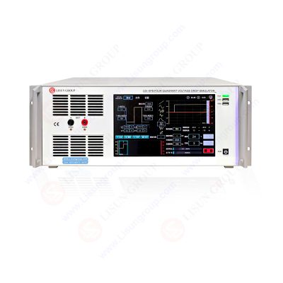
Fyra-kvadrant bipolär spänningsvariationssimulator
Ocuco-landskapet LISUN LIS‑APS‑4010K300 Four‑quadrant bipolar voltage simulator is a typical model of this product series. It provides ±40 V DC/AC output, rated current from 0 to ±10 A and frequency coverage from DC to 300 kHz, suitable for immunity testing of most 12‑V on‑board ECUs, sensors and BMS components. It is equipped with a 10.1‑inch Chinese‑English Android capacitive touch screen and supports remote PC control for automatic test‑system integration. Comprehensive protection functions including overcurrent, overvoltage, short‑circuit and overtemperature are implemented to prevent damage to samples and equipment caused by mis‑operation. Its key technical parameters are listed in Table 1.
| Parameterobjekt | Specifikation |
|---|---|
| Utgång Karakteristisk | Four‑quadrant bipolar, bidirectional energy flow |
| Nominell utgångsspänning | ±40 V DC/AC |
| Nominell utgångsström | 0~±10 A |
| Transient Peak Current | 2 times rated current, duration 20~200 ms |
| Sine‑Wave Frequency Range | DC~300 kHz, output error<0.1% |
| Output Mode & Accuracy | CV, CC; output accuracy 0.05%; setting resolution 1 mV / 1 mA |
| Voltage Slew Rate | ≥15 V/µs |
| Source Impedance Adjustment Range | 0 mΩ~500 mΩ, 1 mΩ resolution, accuracy<±5% |
| Voltage Ripple & Noise | <10 mVrms, noise<30 mVpp |
| Maximum Combined‑Wave Editing Steps | 500 steg |
| Minimum Configurable Time Step | 5 µs |
| Styrsystem | 10.1‑inch Android touch screen, PC remote control supported |
| Skyddsfunktioner | Overcurrent, overvoltage, short‑circuit, overtemperature protection |
Application of Four‑quadrant Bipolar Voltage Simulator in Automotive Electronics Immunity Testing
The Four‑quadrant bipolar voltage simulator can fully cover electrical immunity test items defined in GB/T 28046.2‑2019, ISO 16750‑2:2023, ISO 7637‑2:2021, LV124, GS95024‑2 and other specifications, mainly including battery voltage fluctuation simulation, cranking voltage drop simulation, reverse‑battery polarity‑reversal test, power‑line transient pulse immunity test and high‑frequency ripple superposition immunity test.
In cranking condition simulation, power‑supply voltage drops rapidly and recovers during engine cranking. The Four‑quadrant bipolar voltage simulator generates multi‑step composite waveforms to reproduce the full sequence of fast voltage drop and slow recovery. Adjustable source impedance simulates real harness voltage drop to test whether ECUs suffer reset, crash or communication failure under severe power‑supply variation. For polarity‑reversal tests, output voltage smoothly transitions from positive to negative with synchronized current commutation, simulating battery reverse‑connection faults and verifying reliability of reverse‑polarity protection circuits inside DUTs. For P2b and P4 pulses defined in ISO 7637‑2, microsecond‑scale voltage slew rate enables accurate reproduction of steep pulse edges, while regenerative current from DUTs is absorbed to avoid waveform distortion commonly seen with conventional power supplies.
High‑frequency ripple superposition test is essential for verifying immunity performance of automotive electronics. The Four‑quadrant bipolar voltage simulator superimposes DC‑to‑300 kHz AC ripple onto DC bias voltage. Closed‑loop sampling probes acquire actual voltage 10 cm away from DUT for closed‑loop control, ensuring ripple amplitude at DUT terminals strictly complies with standard requirements and eliminating amplitude attenuation caused by test leads, which greatly improves test accuracy. The Four‑quadrant bipolar voltage simulator can also simulate regenerative conditions of energy‑storage devices and motor drives by absorbing feedback energy from DUTs to emulate motor generation and energy‑storage discharge scenarios. Beyond automotive electronics, it can be applied in power‑supply adaptability tests for rail transit, aerospace, industrial control and medical electronics.
Analysis of Test Application Effect
Compared with conventional test setups of storage battery plus signal generator, the Four‑quadrant bipolar voltage simulator digitizes and stores all test conditions. Parameters such as impedance, waveform and time sequence can be directly recalled from saved project files. Fully identical test conditions can be achieved across different operators and test sessions, significantly improving test reproducibility and reducing systematic errors introduced by manual loop assembly. Built‑in oscilloscope and FFT analysis reduce external instrument quantity, lower test‑bench complexity and minimize debugging work related to instrument trigger synchronization.
In practical sample testing, bumpless quadrant transition of the Four‑quadrant bipolar voltage simulator avoids extra voltage spikes during polarity reversal and pulse switching. No additional interference is injected into DUTs, enabling accurate capture of real immunity failure phenomena. Nevertheless, for complete ISO 16750‑2 test campaigns, auxiliary equipment shall be deployed and full test systems shall be constructed in accordance with specifications to guarantee compliance.
Slutsats
As functional complexity of automotive electronic components keeps increasing, higher requirements are imposed on power‑supply immunity of on‑board devices. Traditional unipolar power supplies can no longer satisfy all standard test requirements. Featuring bidirectional energy flow, bumpless four‑quadrant transition, programmable waveform, adjustable source impedance and wide‑band ripple superposition, the Four‑quadrant bipolar voltage simulator reconstructs real‑world vehicle power‑supply disturbance environment and provides reliable hardware support for immunity validation of ECUs, BMS and other automotive electronic assemblies. As a representative model of this series, the LISUN LIS‑APS‑4010K300 Four‑quadrant bipolar voltage simulator covers most electrical‑load immunity tests for mainstream 12‑V automotive electronic components. It delivers prominent engineering value for improving reliability of automotive electronic products, shortening R&D validation cycles and completing compliance tests for domestic and international standards. With popularization of 48‑V mild‑hybrid systems, higher‑voltage Four‑quadrant bipolar voltage simulators will play an increasingly important role in next‑generation on‑board electronics testing.html>
Din e-postadress kommer inte att publiceras. Behövliga fält är markerade *

 Engelska
 中文简体
中文简体 Русский
 Español
 Português
 Türkçe
 العربية
 Deutsch
 Polski
 Italiano
 Français
 한국어
한국어 ไทย
ไทย Tiếng Việt
 日本語
日本語






